文書の過去の版を表示しています。
目次
DSCore specification
About this
DSCore is a core hardware and software of DSmain and DCC/MM2 Shield. It is implemented to AVR micro controller. You can see the AVR chip on the board.
Features
- Support DCC and Marklin digital (Marklin Motorola 2) protocol
- Easy to control from Arduino
- Include booster functionality
- Support AVR ATMEGA88/ATMEGA328, not required external crystal.
- Communicate via SPI mode 0, LSB first, 1Mbps(default tested speed. The speed depends on your SPI master).
Specification
| DCC | Marklin Motorola 2(MM2) | notes | |
|---|---|---|---|
| speed step | 14, 28, 128 | 14 | |
| function | F0-F28 | F0-F16 | |
| locomotive address | 1-9999 | 1-255 | |
| accessory address | 1-2044 | 1-320 | |
| CV | write only* | developping | |
| Preamble pulse | long preamble supported | none |
* Supported only service mode packet and direct mode
Pulse generator
- walk-around output every 5 milliseconds
- micro second pulse control to generate DCC and MM2 pulse.
- Deadtime 2.5us per every pulses.
Protection function
- Emergency Stop button
- Restart button
- Motor driver's(TB6643KQ/TB6568KQ) protection (Thermal and short circuit protection)
- Short circuit protection using Poly switch (DSmain and DSpi only)
SPI communication specification
DScore defines the following specification.
- Address size is 16bits (2 bytes, word), the range is 0x0000 to 0xFFFF
- Speed size is 16bits (2 bytes, word), the range is 0 to 1023.
- A CRC byte is calculated from previous bytes.
DScore communicates with SPI master. The following shows DScore in DCC/MM2 shield communicates with Arduino UNO micro controller via SPI wire.
DScore uses the following address map. This map assigns the locomotives and turnouts (accessories) of each protocol.
| Address type | Address range | Address means | |
|---|---|---|---|
| Marklin Motorola 2 locomotive | 0x0000-0x07FF | 0(0x0000) - 255(0x00FF) | |
| DCC locomotive | 0xC000-0x1FFF | 0(0xC000) - 9999(0xE70F) | |
| Marklin Motorola 2 accessory | 0x3000-0x37FF | 1(0x3000) - 320(0x3140) | |
| DCC accessory | 0x3800-0x3FFF | 1(0x3800) - 2044(0x3FFC) |
SPI master can control DSCore via SPI. DSCore supports SPI mode 0 and LSB First. SPI master must send the frame in accordance with the following frame specification. The first byte of the frame means the frame command and size. The upper 4 bits mean command bits and the lower 4 bits mean the frame size.
| Frame category | Frame size | Frame detail | |
|---|---|---|---|
| Power on | 2 bytes | 0xF2 0xF2 | |
| Power off | 2 bytes | 0x02 0x02 | |
| Locomotive speed | 6 bytes | 0x16 ADDR_LOW ADDR_HIGH SPEED_LOW SPEED_HIGH CRC | |
| Locomotive speed ex | 7 bytes | 0x17 ADDR_LOW ADDR_HIGH SPEED_LOW SPEED_HIGH EX_CMD CRC | |
| Locomotive function | 6 bytes | 0x36 ADDR_LOW ADDR_HIGH FUNC_NO POWER CRC | |
| Locomotive direction | 5 bytes | 0x55 ADDR_LOW ADDR_HIGH DIR CRC | |
| Accessory | 6 bytes | 0x26 ADDR_LOW ADDR_HIGH 0x00 SWITCH CRC | |
| CV write | 5 bytes | 0x40 ADDR_LOW ADDR_HIGH CV_VALUE CRC |
| Definition | means |
|---|---|
| ADDR_LOW | low byte of Address word |
| ADDR_HIGH | high byte of Address word |
| SPEED_LOW | low byte of Speed word |
| SPEED_HIGH | high byte of Speed word |
| FUNC_NO | function number |
| DIR | direction. FWD means 1, REV means 2 |
| POWER | ON means 0. OFF means 1. |
| SWITCH | 0 means diverging. 1 means straight. |
| CVADDR_LOW | low byte of CV address. Set 0x00. |
| CVADDR_HIGH | high byte of CV address. If DCC use, set 0xC0. if DS-DCC decoder uses, set0xC0. |
| CV_VALUE | CV value |
| EX_CMD | 0:Default(DCC28, MM2 14), 1:DCC14/MM2 28, 2:DCC128 |
| CRC | The all bytes excluding the CRC byte calculates with exclusive-or(XOR). |
AVR programming requirements
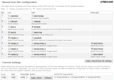
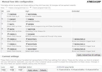
If you want to program DSCore firmware to AVR chip, you also need to write fuse bit. Fuse bit requirements are the following. The main point is to disable CKDIV8 bit. This bit is enable at default.
FUSE bit configuration:
| AVR chip | Extended | High | Low | Notes |
|---|---|---|---|---|
| ATMEGA88 | 0xF9 | 0xDF | 0xE2 | supporets DSCore firmware rev.156 |
| ATMEGA328 | 0x07 | 0xD9 | 0xE2 | supporets DSCore firmware rev.178 or later |


