SmileSoundの開発では、サウンドデコーダという複雑な機能を実現するためには、マイコン(RP2040)の資源をフルに活用する事が、様々な機能を実現するうえで重要になってきます。現状使用している、NMRA DCC Libraryには大きなハンデがあります。このDCC受信ライブラリは、汎用性を重視しているので、DCCパルスの認識・受信処理を外部割込によるソフトウェアで実装しています。このため、CPUを占有する時間が長く、他の処理の動作を妨げることが多々あります。外部割込は、おおよそ58us~100us程度で発生するので、高性能なRP2040であっても、それなりにヘビーであります。
通常、このような処理はソフトウェアではなく、タイマー周辺機能にある「インプットキャプチャ」を使う事が一般的です。しかし、インプットキャプチャは、マイコンごとに設定が大きく異なり、さらにいくつかの制約により、DCC用には向かない機能となっている場合もあります。NMRA DCC Libraryがインプットキャプチャを用いないのは、そのような理由からです。
さて、SmileSoundでは、RP2040専用で実装するのですから、RP2040固有の機能を使っても特に支障はありません。そこで、インプットキャプチャを実装しようと思ったのですが、なんとRP2040にはインプットキャプチャがない!FPUもなければインプットキャプチャもないということで、非常にシンプル側に攻めたマイコンとなっています。しかし、ご安心を、RP2040には、PIOと呼ばれるユーザーカスタム可能な周辺機能を使用することができます。そこで、pioを使って、DCCのパルス幅をカウントし、NMRA DCC Libraryのパケット処理部に流し込む機能を実装していきます。
まず、pioとは何ぞや?という話をするのは、他のサイトでたくさん解説されているので割愛します。
pioを使って実装するにあたり、どうDCCパルスを解釈させるかという事を考えます。DCCパルスは、半周期58us幅の”1″パルスと、半周期95us~9900us幅の”0″パルスの2つがあります。半周期のパルス幅(duty)に着目して、読み出す実装とします。

次に、pioの制約です。pioのアセンブラプログラムで使えるX・Yのレジスタは、なんと0-31の値しか使えません。また、データを蓄えるFIFOは32bit×8段、シフトレジスタは32bitなので、4bitでパルス幅をカウントしたいと思います。おおよそ200us程度までカウントできれば問題ないので、14.5usで1dというようにして実装します。
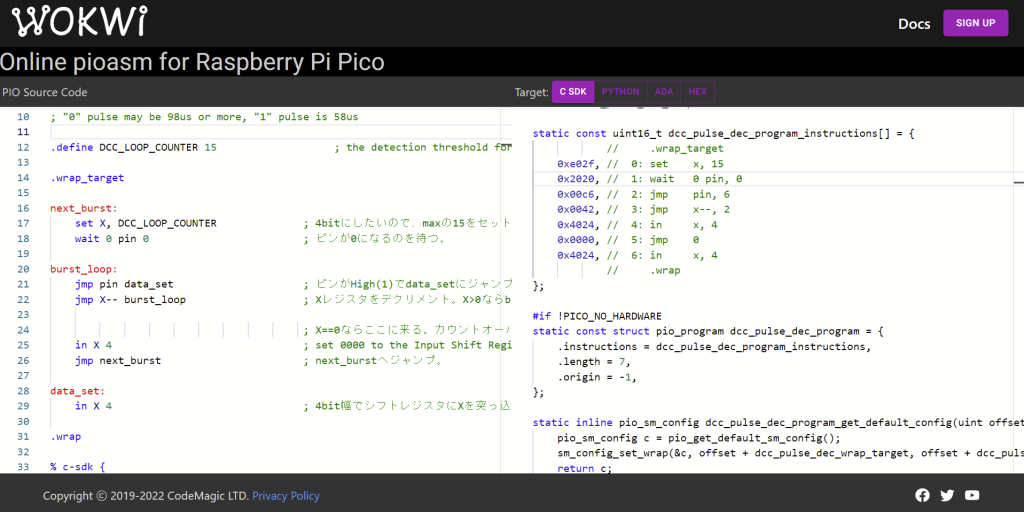
pioのアセンブラプログラムを実装するのに、PCにいろいろインストールする必要があるのですが、面倒なので、Webに置いてあるアセンブラpioasmを使わせてもらいます。左側にpioasmを書くと、右側にC言語のヘッダに自動変換してくれる優れものです。

実際のpioasmのソースは以下です。4bit幅でカウントして、シフトレジスタに格納(IN X 4)しているので、32bitあたり8個のパルス幅を格納できます。8個溜まると、自動的にRX FIFOにpushされるautopush機能を初期化時に有効にしてます(sm_config_set_in_shift )。RX FIFOは8段となるように設定変更してますので、合計で64個のパルス幅がカウント可能になってます。
;
; Copyright (c) 2022 DesktopStation Co., Ltd.
;
; SPDX-License-Identifier: BSD-3-Clause
;

.program dcc_pulse_dec

; Repeatedly get 4bit word of data from the DCC pulse
; "0" pulse may be 98us or more, "1" pulse is 58us

.define DCC_LOOP_COUNTER 15                   ; the detection threshold for a 'frame sync' burst

.wrap_target

next_burst:
    set X, DCC_LOOP_COUNTER              ; 4bitにしたいので、maxの15をセット。ちなみにデクリメントしかできない。
    wait 0 pin 0                         ; ピンが0になるのを待つ。

burst_loop:
    jmp pin data_set                     ; ピンがHigh(1)でdata_setにジャンプ
    jmp X-- burst_loop                   ; Xレジスタをデクリメント。X>0ならburst_loopにジャンプ

                                         ; X==0ならここに来る。カウントオーバーなので、長い0 pulseとみなす。
    in X 4                               ; set 0000 to the Input Shift Register
    jmp next_burst                       ; next_burstへジャンプ。

data_set:
    in X 4                               ; 4bit幅でシフトレジスタにXを突っ込む。溜まると勝手にRX FIFOにpushされる設定。

.wrap

% c-sdk {
static inline void dcc_pulse_dec_init(PIO pio, uint sm, uint offset, uint pin) {
    pio_sm_config c = dcc_pulse_dec_program_get_default_config(offset);


    // PIOのピン設定。
    pio_gpio_init(pio, pin);
    // ピンの設定。inputにする。複数ピンを束ねて設定できるが1ピンのみにする。
    pio_sm_set_consecutive_pindirs(pio, sm, pin, 1, false);

    // 受信FIFOを8段重ねる設定。これで、4x8x8=256文字のデータを一気に受信できるはず。
    sm_config_set_fifo_join (&c, PIO_FIFO_JOIN_RX);

    // ISR(インプットシフトレジスタ)の設定。autopushがミソ。
    sm_config_set_in_shift (&c,
                            true,       // shift right
                            true,       // enable autopush
                            32);        // autopush after 32 bits


    // Map the IN pin group to one pin, namely the `pin`
    // parameter to this function.
    //
    sm_config_set_in_pins (&c, pin);

    // Map the JMP pin to the `pin` parameter of this function.
    //
    sm_config_set_jmp_pin (&c, pin);

    // Set the clock divider to 1 tick per 7.25us(1cnt 14.5us) burst period
    //
    float div = clock_get_hz (clk_sys) / (1.0 / 7.25e-6);
    sm_config_set_clkdiv (&c, div);


    // Load our configuration, and jump to the start of the program
    pio_sm_init(pio, sm, offset, &c);
    // Set the state machine running
    pio_sm_set_enabled(pio, sm, true);
}
%}
生成されたヘッダは以下の通りです。
// -------------------------------------------------- //
// This file is autogenerated by pioasm; do not edit! //
// -------------------------------------------------- //

#pragma once

#if !PICO_NO_HARDWARE
#include "hardware/pio.h"
#endif

// ------------- //
// dcc_pulse_dec //
// ------------- //

#define dcc_pulse_dec_wrap_target 0
#define dcc_pulse_dec_wrap 6

static const uint16_t dcc_pulse_dec_program_instructions[] = {
            //     .wrap_target
    0xe02f, //  0: set    x, 15
    0x2020, //  1: wait   0 pin, 0
    0x00c6, //  2: jmp    pin, 6
    0x0042, //  3: jmp    x--, 2
    0x4024, //  4: in     x, 4
    0x0000, //  5: jmp    0
    0x4024, //  6: in     x, 4
            //     .wrap
};

#if !PICO_NO_HARDWARE
static const struct pio_program dcc_pulse_dec_program = {
    .instructions = dcc_pulse_dec_program_instructions,
    .length = 7,
    .origin = -1,
};

static inline pio_sm_config dcc_pulse_dec_program_get_default_config(uint offset) {
    pio_sm_config c = pio_get_default_sm_config();
    sm_config_set_wrap(&c, offset + dcc_pulse_dec_wrap_target, offset + dcc_pulse_dec_wrap);
    return c;
}

static inline void dcc_pulse_dec_init(PIO pio, uint sm, uint offset, uint pin) {
    pio_sm_config c = dcc_pulse_dec_program_get_default_config(offset);
    // PIOのピン設定。
    pio_gpio_init(pio, pin);
    // ピンの設定。inputにする。複数ピンを束ねて設定できるが1ピンのみにする。
    pio_sm_set_consecutive_pindirs(pio, sm, pin, 1, false);
    // 受信FIFOを8段重ねる設定。これで、4x8x8=256文字のデータを一気に受信できるはず。
    sm_config_set_fifo_join (&c, PIO_FIFO_JOIN_RX);
    // ISR(インプットシフトレジスタ)の設定。autopushがミソ。
    sm_config_set_in_shift (&c,
                            true,       // shift right
                            true,       // enable autopush
                            32);        // autopush after 32 bits
    // Map the IN pin group to one pin, namely the `pin`
    // parameter to this function.
    //
    sm_config_set_in_pins (&c, pin);
    // Map the JMP pin to the `pin` parameter of this function.
    //
    sm_config_set_jmp_pin (&c, pin);
    // Set the clock divider to 1 tick per 7.25us(1cnt 14.5us) burst period
    //
    float div = clock_get_hz (clk_sys) / (1.0 / 7.25e-6);
    sm_config_set_clkdiv (&c, div);
    // Load our configuration, and jump to the start of the program
    pio_sm_init(pio, sm, offset, &c);
    // Set the state machine running
    pio_sm_set_enabled(pio, sm, true);
}

#endif
これを、Arduinoでコンパイルできるようなスケッチを書きました。RP2040の開発環境は、お馴染みのearlephilhower版Arduino-picoライブラリです。Arduino IDEで簡単にRP2040のソフトを書けるので便利です。
#include <stdio.h>
#include "pico/stdlib.h"
#include "hardware/pio.h"
#include "dcc_pulse_dec.h"

#define PIN_DCC				2

//  pioasmを使って、dccpulse.pioからdcc_pulse_dec.hを生成しています。
//  https://wokwi.com/tools/pioasm

PIO gPio;
uint gPio_SM;
unsigned long gRecvPulseWidth[8];

void setup()
{
	//PIOのch 0を確保
    gPio = pio0;

    //アセンブラのPIOプログラムへのアドレス
    uint offset = pio_add_program(gPio, &dcc_pulse_dec_program);

    // 空いているステートマシンの番号を取得
    gPio_SM = pio_claim_unused_sm(gPio, true);

	// PIOプログラムを初期化
	dcc_pulse_dec_init(gPio, gPio_SM, offset, PIN_DCC);

	//デバッグ用シリアル
	Serial.begin(115200);


}


void loop()
{

	if( pio_sm_is_rx_fifo_full(gPio, gPio_SM) == true)
	{

		for( int i = 0; i < 8; i++)
		{
			gRecvPulseWidth[i] = pio_sm_get(gPio, gPio_SM);
		}

		Serial.println("RECV:");

		for( int i = 0; i < 8; i++)
		{
			print32bits(gRecvPulseWidth[i]);
		}

	}
	else
	{
		//Serial.print(".");
	}

}

void print32bits(unsigned long inBuf)
{

	Serial.print( getUS(inBuf & 15) );
	Serial.print(" ");
	Serial.print( getUS((inBuf >> 4) & 15) );
	Serial.print(" ");
	Serial.print( getUS((inBuf >> 8) & 15) );
	Serial.print(" ");
	Serial.print( getUS((inBuf >> 12) & 15) );
	Serial.print(" ");
	Serial.print( getUS((inBuf >> 16) & 15) );
	Serial.print(" ");
	Serial.print( getUS((inBuf >> 20) & 15) );
	Serial.print(" ");
	Serial.print( getUS((inBuf >> 24) & 15) );
	Serial.print(" ");
	Serial.println( getUS((inBuf >> 28) & 15) );

}

unsigned long getUS(unsigned long inVal)
{
	return (15 - inVal) * 14;

}
RP2040ボードで、GPIO2にDCCパケット(3.3Vのロジックレベル信号に回路で調整してくださいね)を流し込んで動かすと、シリアルモニタにパルス幅をひたすら出力していきます。

だいたい、42-56あたりが”1″で、98以上は”0″という形で解釈すれば良いと思います。
11111111 ←プリアンブル
11111111 ←プリアンブル
0  ←StartBit
11000001
0  ←StartBit
01101110
0  ←StartBit
00111111
0  ←StartBit
10011010
0  ←StartBit
00001111
1
1  ←StopBit
パルス幅を置き換えて、上記のようなパケットデータが出てきたら、プリアンブルとスタートビット・ストップビットを除去して、「11000001 01101110 00111111 10011010 00001111」というのが出てくるので、これを弊社が昔作った、Webパケット解析器に突っ込むと以下のように分析してくれます。狙ったとおりの感じですね。

ということで、まだNMRA DCC Libraryに突っ込む処理は入れてませんが、上記のサンプルをzipで固めておきました。


