How to prepare
- Preparation to assemble
- Assemble Arduino board and CAN-BUS Shield
- Check the wiring of Railuino and marklin hardwares
- Assemble CAN cable
- Procedure to prepare S88 decoder
- Procudure to prepare softwares
Are you using AnalogDC locomotives? See Prepare for AnalogDC page.
Preparation to assemble
You need below hardwares to run Desktop Station.
- Arduino board(duemilanove328 or UNO R3 or compatible one, for example Arduino UNO R3, Akiduki's AT-MEGA board) but Leonardoa and the comaptible one may not be suitable with some CAN-BUS Shield.
- CAN-BUS Shield (Sparkfun, Watterott, Seeedstudio).
- USB cable (suitable with your arduino board)
- Windows xp, Vista, 7 or 8 PC. Please install .NET Framework 2.0 runtime package if not installed.
- marklin 60113 Anschlussbox(Digital connection box)
- Power supply for 60113. For example, marklin 66361. 66361 spec is 18VDC 36VA.
- CAN cable (need to connect between 60113 and CAN-BUS shield. If you live in EU, you can buy watterott's Railuino cable kit. Assemble guide is available here.)
You need below softwares to run Desktop Station. You can get these softwares free of charge.
- Arduino IDE (including usb serial driver)
- Railuino
- Desktop Station
- If not installed, .NET Framework 2.0 runtime package
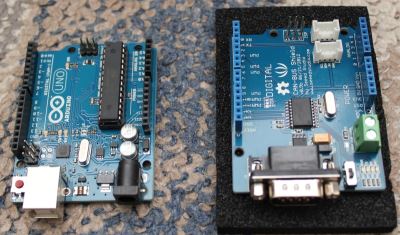
Assemble Arduino board and CAN-BUS Shield.
Assemble Arduino board and CAN-BUS Shield physically.
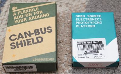
Box images.
Open a box.
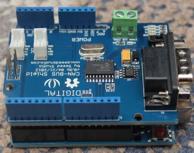
Assembled Arduino UNO and CAN-BUS Shield.
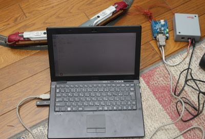
Check the wiring of Railuino and marklin hardwares.
Please check the wiring of Railuino and marklin hardwares. Power of Arduino board and CAN-BUS Shield is provided via USB cable, it's a bus. power. Not use DC jack on the arduino board.
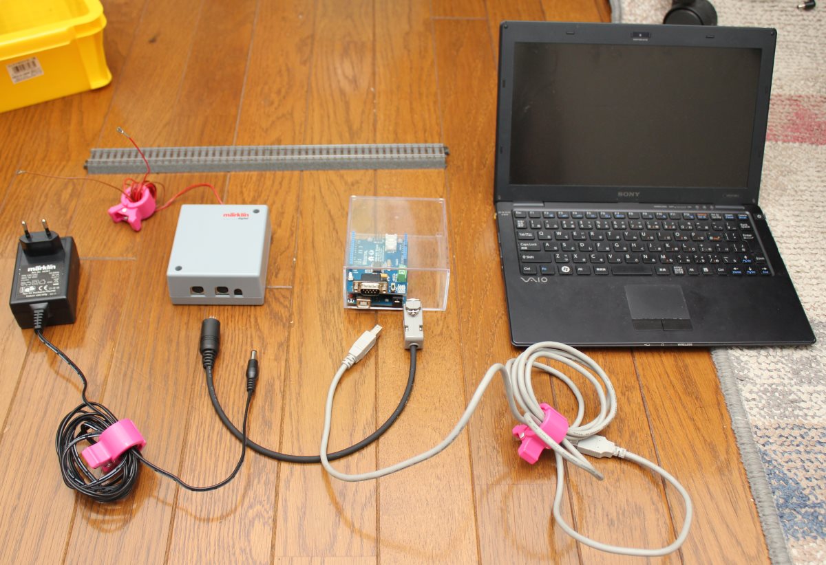
Example before wiring.
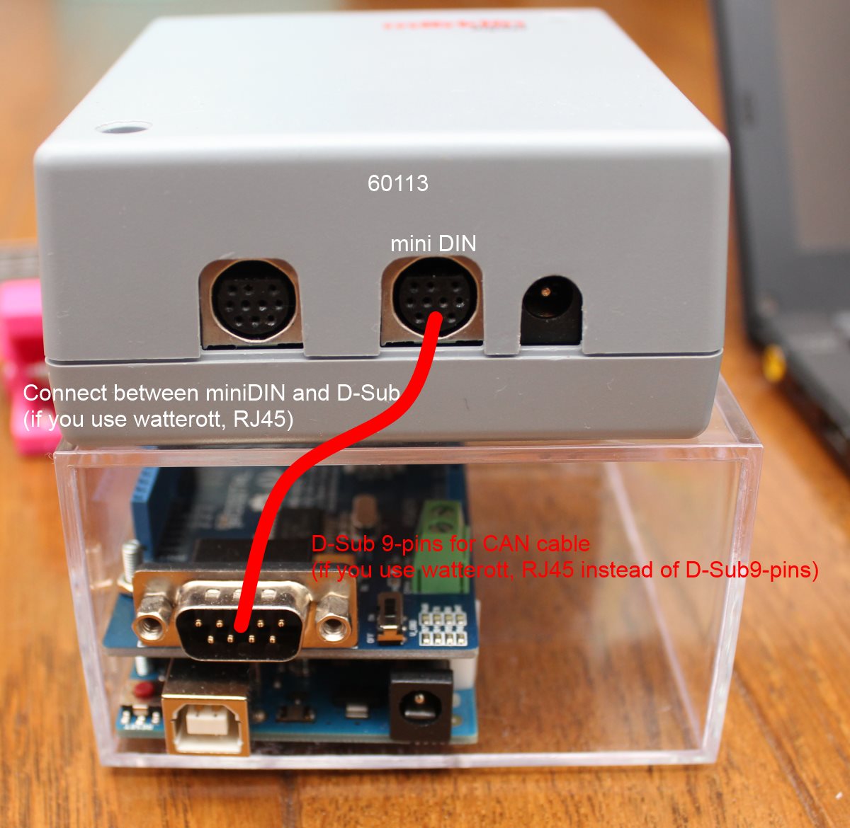
Wiring example between 60113 and CAN-BUS Shield.*
*NOTE
Please note that CAN cable's D-Sub or RJ45 connector is used instead of CAN connector in this case. Typically, D-Sub 9 Pin uses as serial port. Also RJ45 uses as Ethernet. Do not misunderstand.
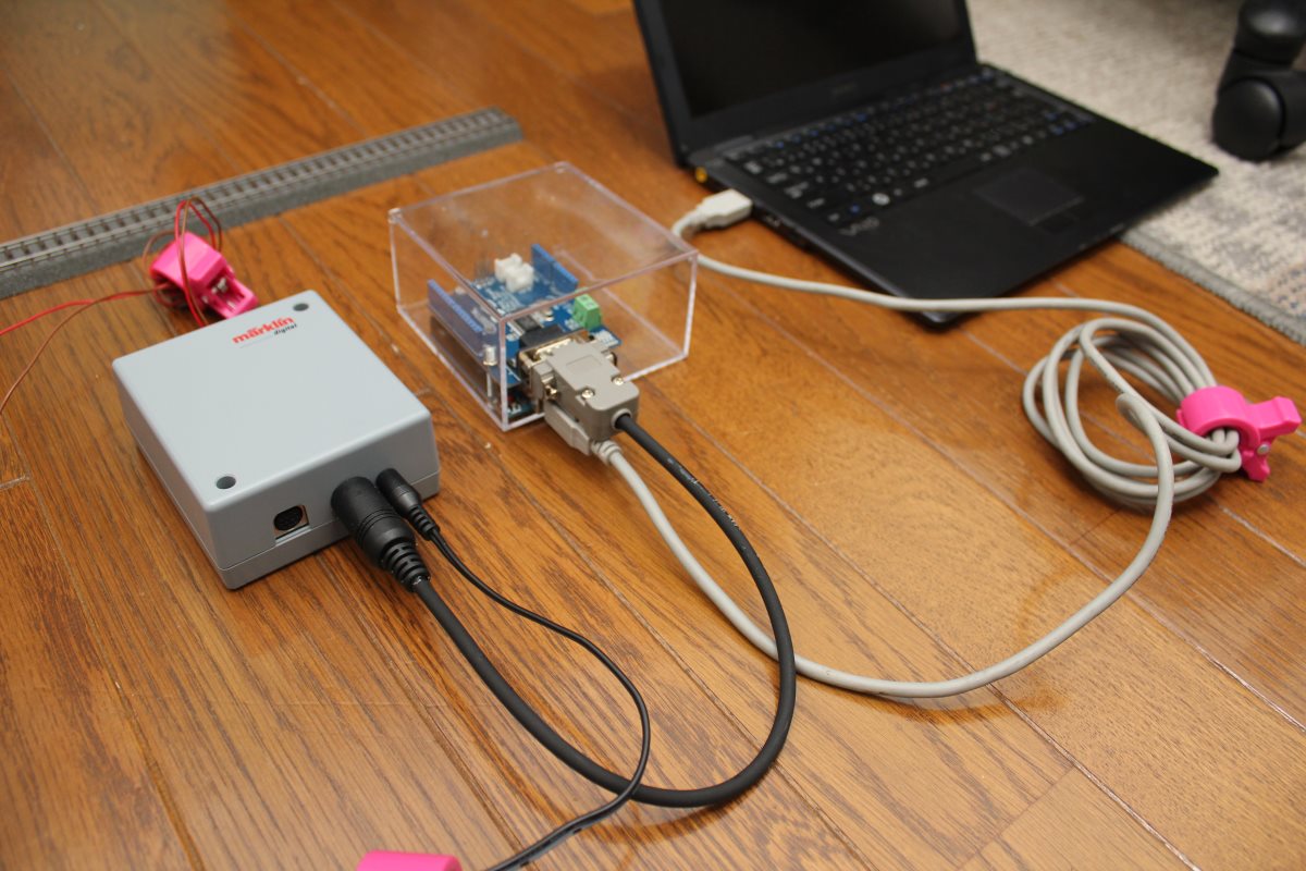
Wired example.
Assemble CAN cable
CAN cable is not in sale. You need to take parts of CAN cable and assemble it like below example. This example describes how to assemble CAN cable forSparkfun's. If you had watterott's shield, please check watterott's description. The difference of watterott's is the connector beside of CAN-BUS Shield. This page describes the connector as D-Sub 9pin.
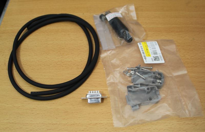
To make CAN cable, you need these components.
miniDIN 10-pins socket and D-SUB 9-pins socket. Also need 4-pin conductor cable.
Table: Parts list example for a cable between 60113 and CAN-BUS Shield.
| Parts name | Price | Notes |
| miniDIN 10-pin (MP371/10) | JPY330 | Hirose-technical B1F in Akihabara |
| D-Sub 9-pin female socket | JPY50 | Akiduki-denshi in Akihabara |
| D-Sub 9-pin shell | JPY50 | Akiduki-denshi in Akihabara |
| 4-core conductor cable | 1m / JPY105 | Kyu-syu denki in Akihabara |
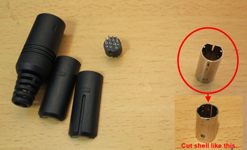
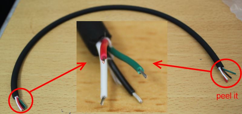
Table: Assignment table of miniDIN pin and D-Sub pin.
| miniDIN 10pin | D-Sub 9Pin | RJ45 | |
| CAN_H | 4 | 3 | 1 |
| CAN_L | 8 | 5 | 2 |
| VCC | 1 | 9 | 8 |
| GND | 2 | 2 | 7 |
| Note | beside 60113 | Seeedstudio, Sparkfun | watterott |
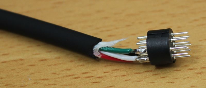
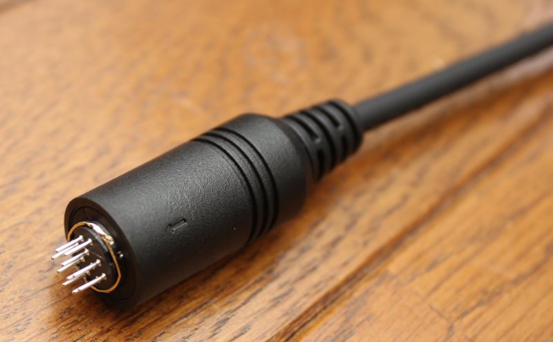
Solder mini-DIN connector and conductor cable. If possible, you have to use a glue gun to connect strongly.
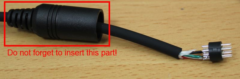
Attention! Do not forget to insert mini-DIN's shell at conductor cable. VERY-IMPORTANT!
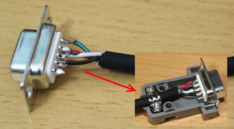
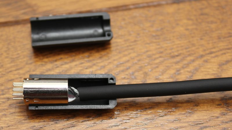
Solder D-Sub 9-pin connector and conductor cable. Also assemble socket and shell.
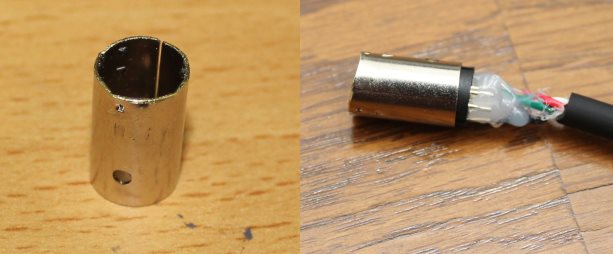
Assemble metal shell and pins. Metal shell which you bought in Japan has to be cut like the above picture.
*Note: Japanese MP371-10 (mini DIN male connector) has opposite direction of pin assignment. If you live in out of Japan, you can get normal connector. Then you don't need to cut metal shell like this. Please check a mini DIN connector that you have.
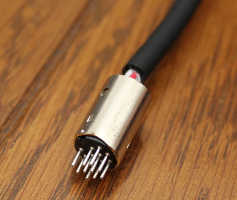
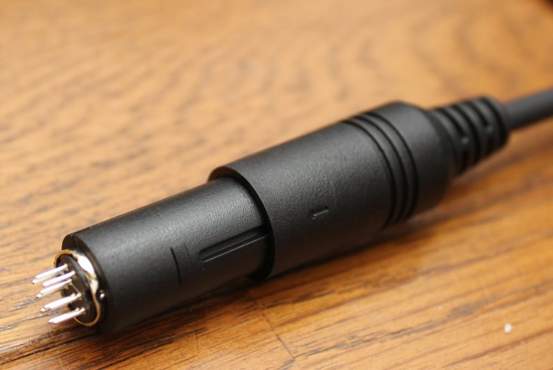
Finish!
Procedure to connect S88 decoder.
Desktop Station requires a S88 interface board to play with S88 function. If not use S88, not reuquired a S88 interface board.
S88 interface board is not on sale. You have to make S88 interface board. Connector of S88 decoder uses 1.27mm pitch 6 pins header which you can get easily in worldwide. Wiring specification of S88 interface is as below.
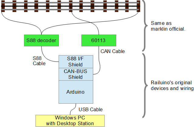
Hardware structure of using S88 function
Wiring S88 cable and Arduino for S88
| Pin name | S88 cable pin | Arduino pin | Notes |
| DATA | 1 | A0 | As using digital input. |
| GND | 2 | GND | |
| CLOCK | 3 | 3 | |
| LOAD | 4 | 4 | |
| RESET | 5 | 5 | |
| VCC(+5V) | 6 | 5V | not using 3.3VDC. |
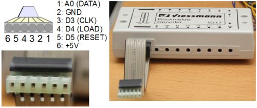
Assignment S88 cable and Arduino.
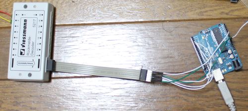
Wiring example.
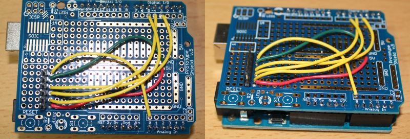
S88 Interface shiled based on prototype shield.
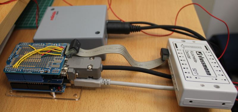
S88 Interface shiled with S88 decoder.
Procedure to prepare softwares
- Download the latest Desktop Station.
Also download Railuino. - Download Arduino IDE 1.0.x. Unzip them to your computer.
- Plug USB connector of your Arduino board to USB port on your computer
- If you plug Arduino board first time, install serial driver software. Serial driver software is included Arduino IDE files. See also arduino.cc
- Unzip Railuino archive file and copy Railuino folder to Arduino IDE's library path.
- Install Desktop Station to your computer. Unzip a Desktop Station ZIP file.
- Compile and Write included Serial Gateway "Serial_RSx.ino" to Arduino board using Arduino IDE. SERIAL GATEWAY sketch named "Serial_RSx.ino" is included Desktop Station's archive zip file. Desktop Station works with this sketch. See also how to upload.
- Upload compiled Serial_RSx.ino to your arduino.
- Connect 60113 and CAN-BUS shield and your PC.
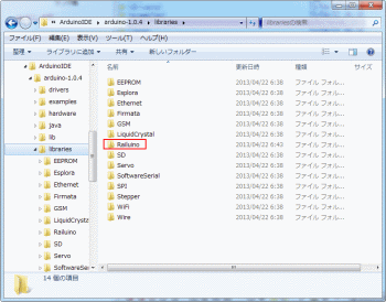
Copy "src" folder in Railuino folder file to Arudino IDE's library folder.
Rename copied "src" folder to "Railuino".
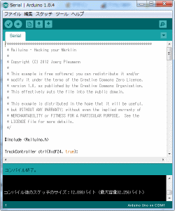
Arduino IDE. Open Serial_RSx.ino and compile it.