Manufacturing procedure
Example of manufacturing
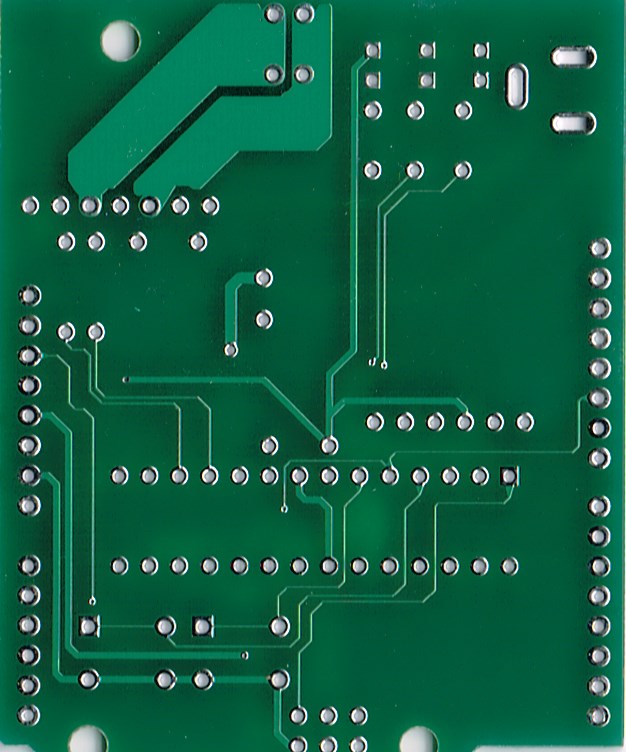
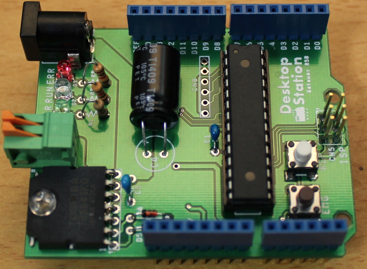
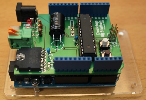
You can find soldered printed circuit board of DCC/MM2 shield as followings. Please refer to solder.


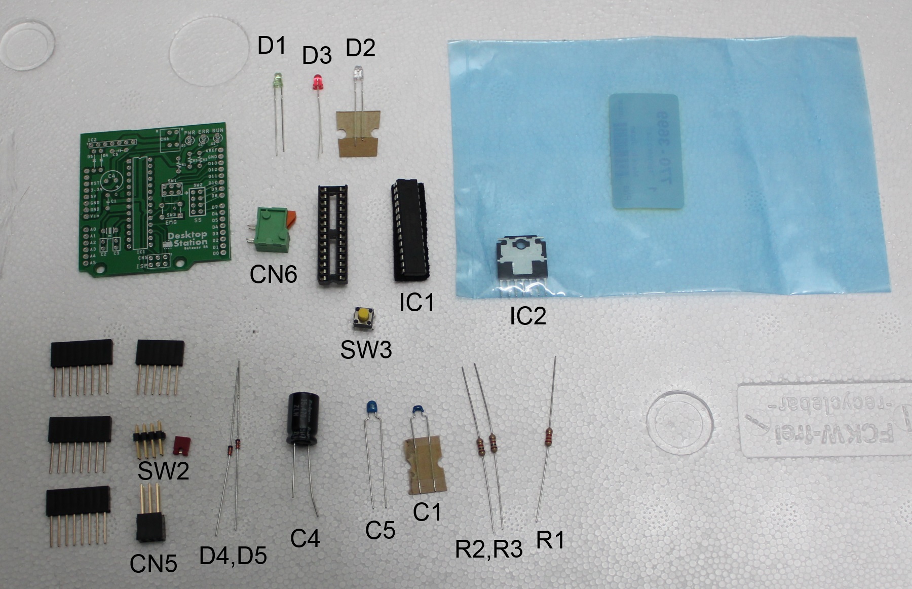
Parts list
| Parts No. | Parts name | Specification |
| R1 | Resistor | 1k Ohm, 3mA(typ) |
| R2 | Resistor | 1k Ohm, 3mA(typ) |
| R3 | Resistor | 1k Ohm, 3mA(typ) |
| C1 | Capacitor | 10V, 0.1uF |
| C2 | nc | |
| C3 | nc | |
| C4 | Capacitor | 35v,220-470uF |
| C5 | Capacitor | 50V,1uF |
| D1 | LED | yellow |
| D2 | LED | red |
| D3 | LED | green |
| SW1 | Jumper | nc |
| SW2 | Switch | Tackt switch |
| SW3 | Switch | Tackt switch |
| CN1 | Connector | 6pin Long header |
| CN2 | Connector | 8pin long header |
| CN3 | Connector | 8pin long header |
| CN4 | Connector | 8pin long header |
| CN5 | Connector | 2x3pin Long socket header |
| CN6 | Connector | 2pin terminal |
| CN7 | DC Jack | DC jack |
| CN8 | RJ45 | S88-N I/F |
| IC1 | IC Socket | 28pin IC socket |
| IC1 | ATMEGA328 | MCU |
| IC2 | TB6643KQ | Motor driver |
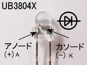
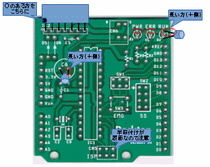
*1 LED polarity shows as the above image.
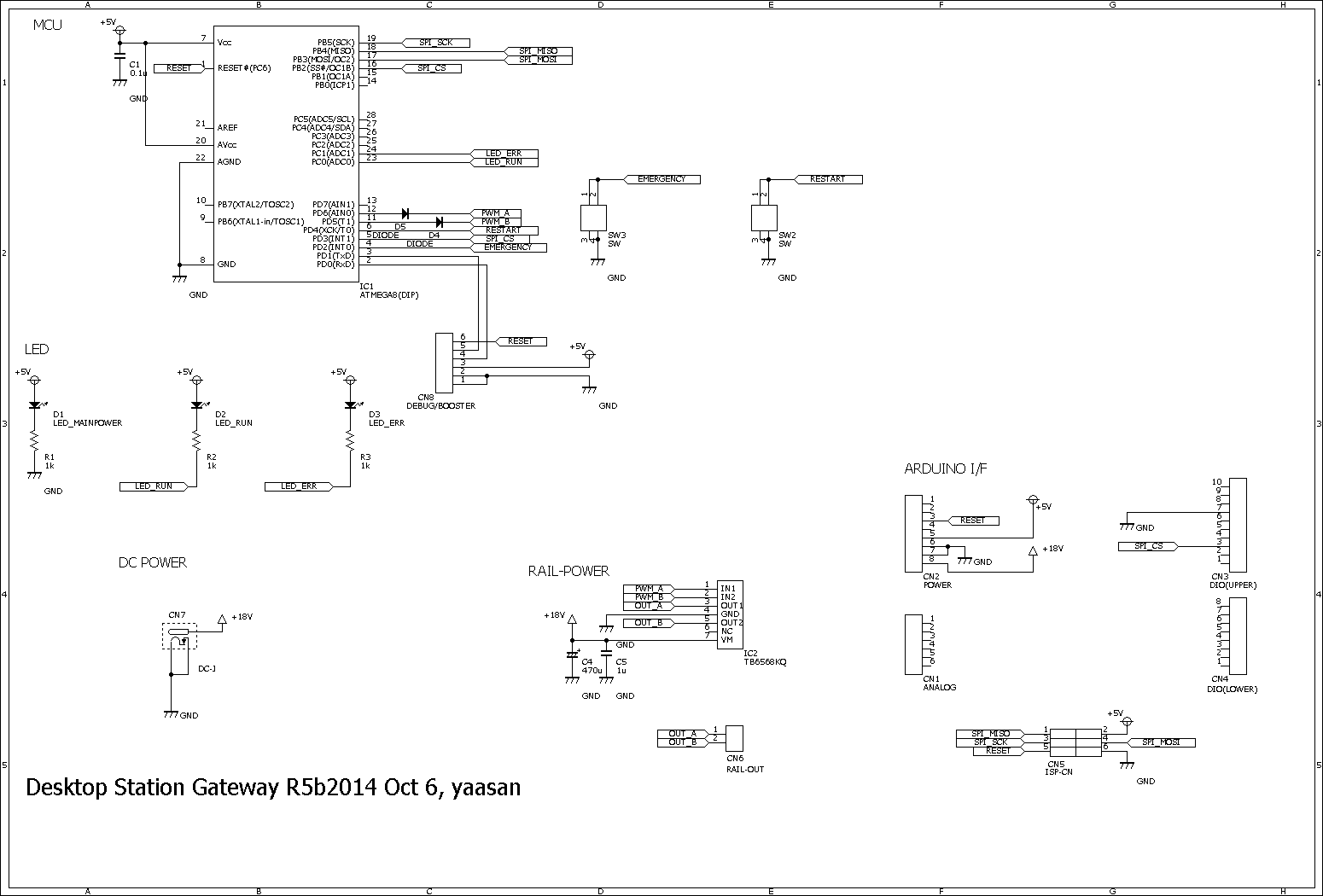
Schematics
Notes for DCC/MM2 shield
Please note the followings.
If you used N gauge, you will use 12V. If H0, use 12V or 15V or 16V or 18V. These voltage is reference.
Maximum absolute current is 3A. Do not exceed 3A temporaly or continuously.
Required devices for DCC/MM2 shield use
 and output connectr is 2,1x5,5mm. The voltage depends on your model railway system. See the followings.
If use marklin H0, 18V powersupply and output current is 2A or more.
If use DCC H0, 12V to 16V power supply and output current is 2A or more.
If use DCC N, 12V power supply and output current is 2A or more.
Procedure to solder
- Arrange solder paste and soldering iron, pcb and parts.
- Solder and assemble base parts. For example, resistor -> LED -> IC -> Capacitor -> Connectors
- Check mistaked of soldering after soldered.
- Insert IC(ATMEGA88) to a socket. Check the silk message and direction of parts.
Procedure to assembly
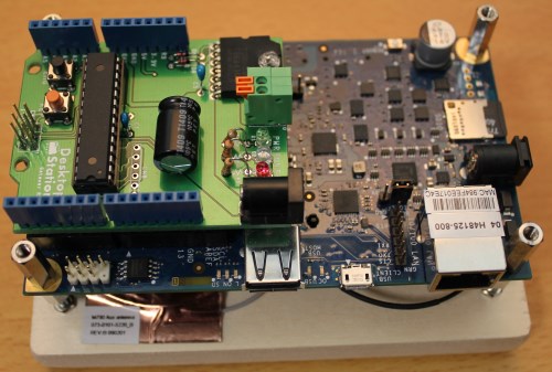
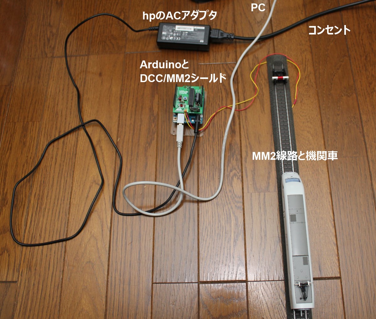
Insert DCC/MM2 shield to Arduino UNO or galileo gen2. Power on the Arduino. Connection of power supply uses Arduino UNO's DC input.
Connecting to DC power supply
DCC/MM2 shield R5 has DC jack. As you know, Arduino board has also DC jack. You can use one of the both DC jack freely. These DC jacks are connected internal pattern. If you want to output higher current, you need to connect DC power supply to DC jack port of DCC/MM2 Shield. Do not use the DC jack of Arduino board then. Because DC power pattern of Arduino board is thin, Arduino board can't support high current. High current means 1.0 Amp or more.
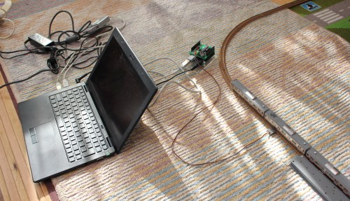
Rail and wiring
In this case, we introduce connection of marklin's CTrack. If you use DC rail, the porality is free.
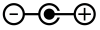
CTrack has the porarity. The porarity is written about the output connector. B means red wire and connects to center rail. O means brown wire and connects to both side rails.
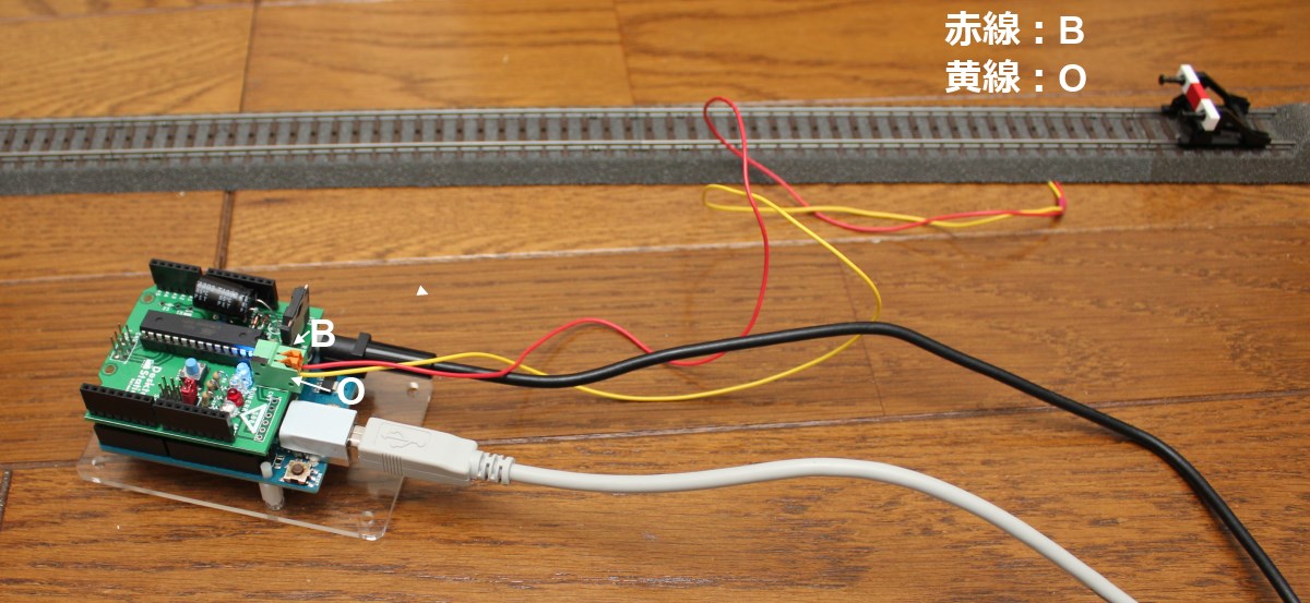
In this photo, red conductor cable appears B(red), yellow cable appears O(brown). Be cause I don't have brown cable, I have used the yellow cable instead of brown one.